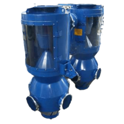
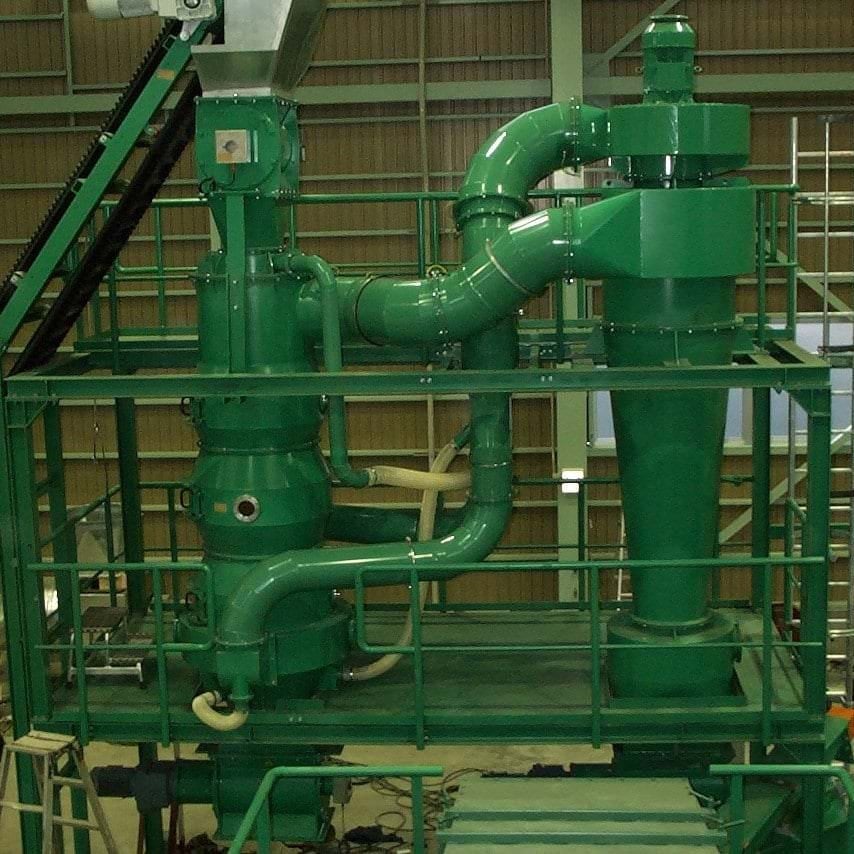
The Circulation Air Cone Separator and the Standard Conical Separator are two similar products for the seperation of heavy materials through air steaming technology.
The heavy material falls through the ascending air stream and is discharged at the separator base. Light material is discharged together with the exhaust air at the upper part of the separator and conveyed via piping to a cyclone. The separation area is constructed on that way that the rising light material and the falling heavy material do not disturb each other. Thereby light material is steadily discharged, even with high loading. During circulation air mode of the cone separator the total sifting air is circulating. Thus there is no discharged air generated. In this mode a sealing of the separator system though a rotary gate valve is necessary. Required air amount and pressing are generated via centrifugal fan.

The product mixture, feeded centred, is distributed evenly over the total width of the separator and reaches the area of separation afterwards. According to the multiple-cross-section-separation procedure the light material is extracted from the product mixture.
- By manufacturing combustibles, it can be used in cement plants as well. Almost without inert-, metal and if required also without hard plastics.
| Type | AxBxC (m) | Air Volume (m³/h) | Throughput (m³/h) | inst. Power (kW) |
| KAU 750 Z 28 | 2,0×0,4×5,0 | 3.600 | 25 | 10 |
| KAU 750 Z 40 | 2,0×4,5×6,0 | 7.200 | 50 | 28 |
| KAU 1000 Z 40 | 2,5×5,0x6,5 | 7.200 | 50 | 28 |
| KAU 1000 Z 63 | 3,0×5,5×8,5 | 14.400 | 50 | 36 |
| KAU 1500 Z 63 | 3,5×6,0x8,5 | 14.400 | 100 | 39 |
| KAU 1500 Z 80 | 4,5×8,0x10,0 | 28.800 | 100 | 66 |
The Standard air cone separator plant is designed for the material separation of heavy and light material up to 80 mm. During the filling procedure the product mixture is introduced centrally and is evenly distributed over the entire width of the separator via a top inlet, until it reaches the separation zone.
| Type | AxBxC (mm)* | Air Volume (m³/h)¹* | Throughput (t/h) ²* | Inst. power (kW) |
|---|---|---|---|---|
| KS 300 ³* | 600x300x150x100 | 500-1000 | <0,75 | <2,2 |
| KS 500 ⁴* | 1000x500x200x150 | 1000-2000 | 0,75-2,5 | 2,2-4,0 |
| KS 750 ⁴* | 1500x750x300x250 | 2000-4000 | 1,5-5,0 | 4,0-7,5 |
| KS 1000 ⁵* | 2000x1000x400x300 | 4000-8000 | 3,0-10,0 | 7,5-15 |
| KS 1500 ⁵* | 3000x1500x600x450 | 8000-16000 | 6,0-20,0 | 15-30 |
1* The throughput (product volume flow refers to combustibles with a bulk density of about 100 kg/m³)
2* Mass flow depends on product
3* Only applicable for dust removal of free flowing products. Construction differs partly.
4* To reduce the air exhaust at the inlet area we use an inlet guiding cone for free flowing products. For limited free flowing products an inlet system like e.g. rotary gate valve has to be used at the inlet area.
5* Feeding system (for example rotary gate valve) for separator is necessary


